Construction

Figure 1: Drawing of housing bottom.

Figure 2: 3D printed housing bottom.
As can be seen in figures 1 and 2, the bottom of the housing is shaped like a funnel with the diameter decreasing towards the opening to fit the plug.

Figure 3: Drawing of housing top.

Figure 4: 3D printed housing top.
The housing top was designed to fit up inside of the neck of a balloon and has a smaller diameter than the rest of the housing. The neck diameter can be adjusted in SolidWorks depending on the size of the balloon it is going to be used in. For this project, we used a balloon with a 1.5-inch neck diameter.

Figure 5: Drawing of housing middle.

Figure 6: 3D printed housing middle.
The middle of the housing is all one diameter and inside it contains a mounting plate for the motor and Arduino board with holes in the mounting plate for air flow. This drawing has been modified from the original drawing to include a keyway in the hole where the beam attaches. This will ensure proper alignment of the beam and housing during assembly.


Figure 7: Drawing of beam half.
Figure 8: 3D printed beam half.
Figure 7 is a modified drawing of the beam which includes a key for the keyway in the housing middle. Again, this is to ensure proper alignment of the beam and the housing during assembly. Additionally, since it was decided to use an aluminum pin rather than a plastic one, both sides of the beam were symmetrical so only one drawing was needed.
Figure 8 shows the left side of the beam before modifications were made. In this picture, the beam has a plastic rod to be inserted into the right side of the beam. The plastic rod was later cut off and a hole was drilled for the aluminum pin.
Since the beam was round, a support base was needed in order for the part to stick to the surface of the printer. After this picture was taken, the support material was peeled off and the beam was ready to go!
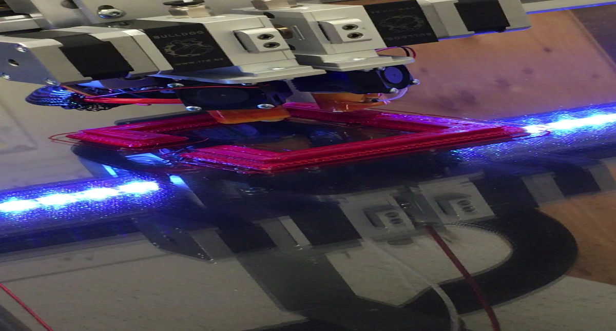
Below is a video clip of the beam being printed.

Beam 3D printing

Figure 9 shows the drawing of the aluminum pin used to support the connection point of the beam halves. A picture of the actual pin was not taken.
Figure 9: Drawing of pin.

Figure 10: Assembly drawing.

Figure 11: Assembled valve.
The video below is an attempt to make a rubber gasket to help the plug seal better.

Making rubber gasket
The housing of this device consisted of the parts shown above. All drawings for this project can also be found in appendix B of the report.
The rest of the valve consisted of components that were purchased (please refer to Appendix C of the report for parts list and budget). These components include the push-pull solenoid, rubber plug, altimeter, microprocessor, the necessary materials for wiring the solenoid and altimeter to the microprocessor, and 9V batteries.
Figure 12 is a functional block diagram showing how the different components are connected. Figure 13 is a picture of what the components actually looked like after being wired.

Figure 12: Functional block diagram.

Figure 13: Valve components.
After wiring and soldering all of the components, the microprocessor was programmed using Arduino software. Below, figure 14 shows a code flow chart, which explains the logic of the code. The pressure in the code can be changed based on the known pressure at a given altitude.

Figure 14: Code flow chart.

