
Testing
Once the valve was constructed, the first test was to determine whether it was capable of holding helium without leaking more than one percent volume per hour. To test this, a small latex balloon was filled up with helium and placed on the valve. The circumference of the balloon was measured at the beginning of the test and every fifteen minutes for thirty minutes. The test was repeated three times.
The device was unsuccessful in meeting the leakage requirements during these tests. During the first test, the balloon lost about 50% of its volume in the first fifteen minutes. However, it was noted that the pressure inside of the smaller balloon is greater than inside of a larger high-altitude balloon. Therefore, for the second two tests, the balloon was only filled half way with helium to reduce pressure. The device did better during these two tests with helium leakage of 14% over thirty minutes, but still did not meet the leakage requirement. Figure 1 illustrates the circumference vs time graph of the balloon for each trial.
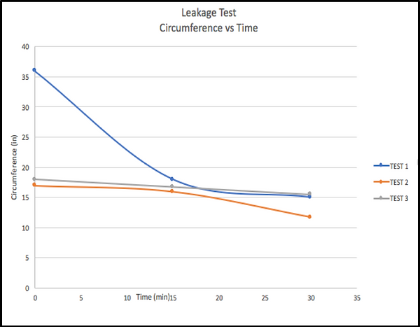
Figure 1: Circumference vs. Time graph
Because the device did not meet the leakage requirement, it was not able to be tested in flight. This means it also did not meet the requirement of maintaining altitude at 70,000 feet for 15 minutes or more. However, it was successful in meeting several of the other requirements!
The device was tested in a pressure chamber to see if it opened and closed at the proper pressure. It tested successfully at 20,000 Pascals, which would be about 33,000 feet altitude. Figure 2 shows a picture of the device inside the pressure chamber.


Figure 2: Device in pressure chamber.
Figure 3: Device tested in dry ice.
Next, the device was tested for its temperature requirement. It was placed in a styrofoam cooler with dry ice and a lid placed over the top, as can be seen in figure 3. The device worked successfully for about an hour. The lowest recorded temperature was -52 degrees Fahrenheit.
The device also met its weight and size requirements with a final weight of 492g (1.08 lbs), as can be seen in Figure 4.
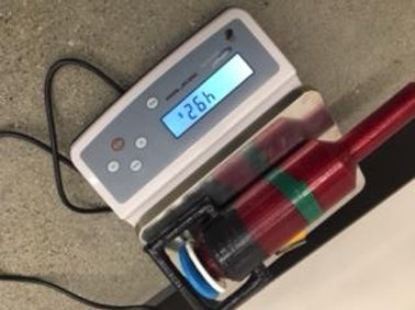

Figure 5: Neck diameter test
Above, in figure 5, it can be seen that the device does indeed fit inside of a 1.5 inch diameter balloon neck.
Figure 4: Valve on digital scale.
Lastly, it can be seen in figures 6 and 7 that the payload support beam was able to exceed its requirement of 12 lbs with a total load of 5510 g (about 12.15 lbs) and did not have a deflection large enough to measure. From the analysis, a deflection of .0002 was predicted.

